What Sets Apart Parallel Redundancy (N+) From Parallel Capacity (N)?
Uninterruptible power supplies (UPS) that operate in parallel supply the load using a shared AC busbar from the outputs of two or more UPS. There are two primary arrangements:
1, Parallel-Capacity (N), in which a number of UPS are used to meet the whole load requirement without the need of any redundancy
2, Parallel-Redundant (N+X), when all UPS equally share the load to satisfy the total load demand. Even if one of the UPS malfunctions, the others can still maintain the load.
Systems with Parallel-Capacity (N) UPS
Because they lack redundancy, "N" configuration options merely enable improved overall capacity by connecting numerous UPS to cooperate. This does not boost system resilience. The quantity of UPS modules employed (sometimes referred to as a Total Power System) determines the overall capacity.
Due to the lack of redundancy, maintaining a parallel-capacity installation requires bypassing the entire UPS system in order to power down one or more modules for maintenance. The load is directly powered by the mains supply during UPS maintenance, leaving it exposed to any interruptions.
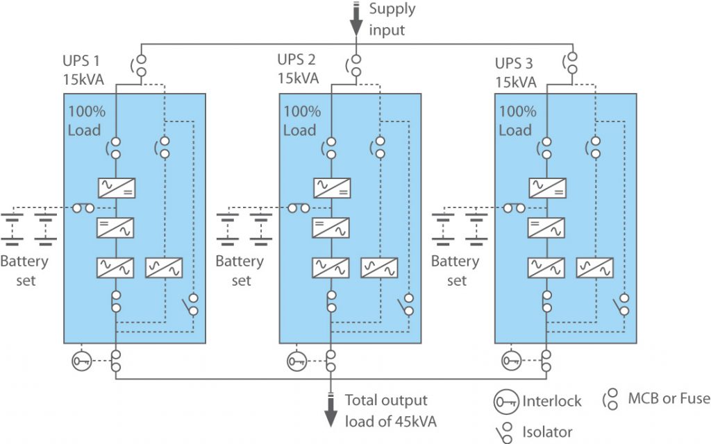
The image below displays a parallel-capable 45 kVA power system made up of three 15 kVA UPSs that are fully loaded.
Systems with Parallel-Redundant (N+X)
Mission-critical applications are frequently protected in data centers, industrial sites, and bigger company processes using 'N+X' configuration options. The fundamental idea behind a parallel-redundant UPS system is that, even in the event that one or more UPS modules fail, it can still supply the important load. This indicates that it can achieve higher availability and MTBF (mean time between failure) in comparison to N capacity installations.
Additionally, this permits UPS maintenance to be performed without affecting the load. While the remaining UPSs continue to carry the load, modules can be powered down for maintenance.
A parallel-redundant 30 kVA N+1 power system with three 15 kVA UPSs sharing an equal amount of the load (10 kVA per UPS) is shown in the graphic below.
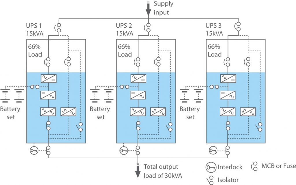 Every UPS distributes the load equally when it is operating normally. Similar to this, each UPS will still share the load if the UPS system needs to run on batteries because each module has its own battery set rather than a shared common battery.
The output AC busbar is automatically disconnected from any failed or malfunctioning UPS modules in a parallel-redundant setup, while the remaining active UPS continue to share the load.
Every UPS distributes the load equally when it is operating normally. Similar to this, each UPS will still share the load if the UPS system needs to run on batteries because each module has its own battery set rather than a shared common battery.
The output AC busbar is automatically disconnected from any failed or malfunctioning UPS modules in a parallel-redundant setup, while the remaining active UPS continue to share the load.
A parallel-redundant system with three 100 kVA UPS supplying a 200 kVA load is shown in the image below. The remaining active units take over the load if "UPS 2" fails.
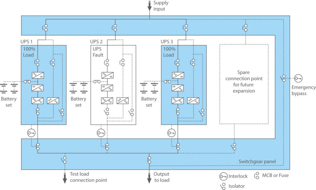
If either "UPS 1" or "UPS 2" were to fail in the aforementioned case, the remaining functioning module would enter an overload state and switch to bypass through its static switch. The load will continue to get power as a result of simultaneously forcing the two defective UPS into bypass.
Additional Redundant UPS Setups
Besides parallel-capacity and parallel-redundant arrangements, there are further options to take into account:
- Isolated-Redundant, also referred to as N+1, is distinct from a parallel-redundant N+1 installation in several ways. In this setup, the primary UPS module supplies power to the load, and the secondary UPS supplies power to the static bypass. The secondary module takes on the entire load when a fault forces the first UPS to switch to bypass.
- Distributed-Redundant, sometimes known as Tri-Redundant, is frequently utilized in big data centers with many megawatts of power. consisting of three or more UPS with independent input and output feeders, and numerous PDUs (and, in some circumstances, static transfer switches) connecting the output buses to the load. Although this topology minimizes single points of failure and allows for concurrent maintenance, it also poses serious load management difficulties.


